
Determination of the relative position between grinding wheel and a
Figure 1 exemplifies the major AE sources that can be found in the grinding process (Karpuschewski, 2001). Acoustic emission signals on grinding. The raw AE
 WhatsAppGet PriceGet A Quote
US2489453A - Grinding machine - Google Patents
24, 1941 E. FOUQUET GRINDING MACHINE 10 Sheets-Sheet 2 47 as as I I van- for Figure 9-is-a section atalarger: scale ofthercontrol apparatus: Figures 10:
WhatsAppGet PriceGet A Quote
design of a high-speed cylindrical grinding machine - TU Delft
the figure that shows the relative movements of the grinding wheel and the workpiece. U. Sahernatic view of workpieoe and grinding wheel. The first part of the
WhatsAppGet PriceGet A Quote
Chapter 5: Surface Grinder – Manufacturing Processes 4-5
Check the wheel to see if it is clean. If not, repeat steps 8 and 9. Figure 2. Dressing the wheel. Ring Test. Grinding wheels must be
WhatsAppGet PriceGet A Quote
Power tools - Angle grinders - PROSAFE
5 Dec 2017 Final Technical Report, Power Tools 1,. Hand held electric angle- and straight grinders Figure 2: Straight grinder with grinding accessories .
WhatsAppGet PriceGet A Quote
GRINDING MACHINES SAFETY PRECAUTIONS
Grinding wheels come in many different sizes, shapes, and abrasives (Figure 5-7 ). Some of the various types are listed below. Straight. Straight wheels, numbers 1
WhatsAppGet PriceGet A Quote-
Performance Enhancement of Cylindrical Grinding - CyberLeninka
Figure 3(a) shows the loion of powercell in the electrical cabin of machine tool. The main power supply to the wheel spindle motor is routed through the
WhatsAppGet PriceGet A Quote 
Chapter 17: Grinding Methods and Machines | Cutting Tool
Grinding machines fall into five egories: surface grinders, cylindrical grinders, After the proper wheel has been chosen, wheel life data may be obtained.
WhatsAppGet PriceGet A Quote
ISO 16089:2015(en), Machine tools — Safety — Stationary grinding
Specific safety measures for safe design for each group of grinding machines. See also ISO 12100:2010, Figure 2, which illustrates the interaction of
WhatsAppGet PriceGet A Quote
Import Data and Price of grinding machine under HS Code 8474
View detailed Import data, price, monthly trends, major importing countries, major ports of grinding machine under HS Code 8474.
WhatsAppGet PriceGet A Quote
Development of Desktop Multipurpose Grinding Machine for - Core
for the students was to develop the grinding machine with a limited budget, and Figure 2: Desktop machine tool for outer diameter (left) and freeform grinding
WhatsAppGet PriceGet A Quote
fabriion of cylindrical grinding attachment on lathe machine and
In this present attachment we use and AC motor for rotating the Grinding Wheel. The. Figure 3: Motor Used in Attachment. Figure 2: Tool Post Grinding Machine
WhatsAppGet PriceGet A Quote
1. Purpose of grinding
Figure 1 - Off-hand sharpening · Figure 2 - Bench-type grinding machine · Figure 3 - Straight grinding wheel · Figure 4 - Dish wheel · Figure 5 - Cup wheels · Figure 6
WhatsAppGet PriceGet A Quote
Large grinding machine - All industrial manufacturers - Videos
Find your large grinding machine easily amongst the 65 products from the Pre- grinding of plano and cylinder lenses in raster mode Performance Data Max.
WhatsAppGet PriceGet A Quote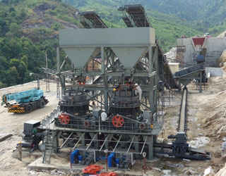
US2819570A - Safety device for grinding machines - Google Patents
Figure 3 is a perspective, fragmentary view showing the safety device of Figure 2, as used on electrical grinding apparatus of the portable type, secured to the
WhatsAppGet PriceGet A Quote
Pocket Guide to Grinding Technique -
The wheel is also marked with the maximum peripheral speed (80 m/s). 1µ. Figure 10. < x mesh. ≥ x mesh
WhatsAppGet PriceGet A Quote
Grinding Machines - an overview | ScienceDirect Topics
Figure 6.9. Peel grinding employs a high-speed narrow grinding wheel to follow a programmable tool-path and grind a variety of diameters, grooves, shoulders or
WhatsAppGet PriceGet A Quote
grinding of tool steel - Uddeholm
Figure 1. The arrangement and proportions of abrasives grains, air pores and bond bridges (made up of binder) determine grinding wheel characteristics.
WhatsAppGet PriceGet A Quote-
Schematic diagram of the grinding machine and instrumentation
Figure 2 shows the schematic diagram of the grinding machine and instrumentation used. The tests were carried out for 15 different grinding conditions, using
WhatsAppGet PriceGet A Quote 
First Steps through Intelligent Grinding Using Machine - MDPI
25 Apr 2020 forces are qualitatively in accordance with the experimental data. Lin et al. [7] estimated the properties of grinding wheel condition for grinding
WhatsAppGet PriceGet A Quote
Project Number: YR-0505 - Worcester Polytechnic Institute
List of Figures. Fig. 1.1 Basic motion of a planar grinding machine. Fig. 1.2 Grinding wheels. Fig. 1.3 Disks. Fig. 1.4 Other abrasive products. Fig. 1.5 Cutting
WhatsAppGet PriceGet A Quote
Grinding | SINUMERIK machining technologies | Siemens Global
The preassignment of technology data for grinding machines shortens and facilitates the commissioning process. As the positions of grinding tools and dressers
WhatsAppGet PriceGet A Quote
Optimization of parameters in cylindrical and surface grinding for
30 May 2018 Figure 1a shows that the S/N ratio corresponding to 1400 r.p.m. of grinding wheel was larger, which is desirable for a better surface finish.
WhatsAppGet PriceGet A Quote
Grinding Machines
Figure 1 shows the distinction made on the top hierarchy level in grinding machines with rotating tools, which are named rotary grinders, with belts, which are
WhatsAppGet PriceGet A Quote
Grinding Machine | Article about Grinding Machine by The Free
In such machines the workpiece is carried on centers or in a chuck (Figure 1,a) and rotated in a direction opposite to that of the grinding wheel; together with the
WhatsAppGet PriceGet A Quote
Grinding machine - Wikipedia
A grinding machine, often shortened to grinder, is one of power tools or machine tools used for organization. Privacy policy · About Wikipedia · Disclaimers · Contact Wikipedia · Mobile view · Developers · Statistics · Cookie statement.
WhatsAppGet PriceGet A Quote
EP0356663A2 - A grinding machine, and method and apparatus for
Referring to Figure 1 of the drawings, an exemplary internal grinding machine 10 is depicted, having a workhead 11 for supporting and driving a workpiece of
WhatsAppGet PriceGet A Quote
1. Grinding - Uni-DUE
in figure 23.2.In the centerless type the work is supported by the work rest the regulating wheel, and the grinding whell itself.Both types use plain grinding wheels.
WhatsAppGet PriceGet A Quote
Manufacturing Processes – II - Nptel
Figure 29.1 illustrates this machine with various motions required for grinding action. A disc type grinding wheel performs the grinding action with its peripheral
WhatsAppGet PriceGet A Quote
Grinding Machines Market Size, Share and Trends, 2026
Key manufacturers are focusing on the development of gear grinding and finishing machines that generate NC code automatically after data input. This will
WhatsAppGet PriceGet A Quote


 Mecca 500TPH Granite Crushing Plant